Installing Heated Floors Under Tile

Installing Heated Floors Under Your Tile Can Be Daunting
In this article, we will explain the major steps on installing our QuietWarmth Peel and Stick Radiant Heat Film for Tile and Glue-Down Flooring. Not only is QuietWarmth great for DIY consumers, but it is also budget friendly while offering heat for your family.
Installation Video:
To start you can view our full installation instructions by clicking on the following image.
Full Installation Guide

Preparing the Job Site
1. Ensure the job site is clean before working with the QuietWarmth® Peel & Stick Radiant Heat, free of any nails,
screws and other sharp debris that could damage the mats.
2. Tile flooring installations must meet subfloor requirements set forth by the Tile Council of North America (TCNA).
What You Will Need
- QuietWarmth® Peel & Stick Radiant Heat mats
- Thermostat: An approved thermostat
- GFCI Breaker (if not part of the thermostat)
- Junction Boxes: Minimum of two boxes required for each room or area. One box (2×4 inch) required for thermostat, one box (4×4 inch) required for electrical connections.
- Tools: Digital ohm meter (multi-meter), wire stripper, screw driver, wood chisel, knife
- Tile installation products (3/8” x 1/4” or greater plastic trowel, mortar, backer board, tile, etc.)
- 12/2 Romex
Electrical Installation
Step 1. GFCI Installation
QuietWarmth® Peel & Stick Radiant Heat mats must be protected by a Class A ground fault circuit interrupter (GFCI). This can be done either by the internal GFCI in the thermostat (as long as it directly controls the mat), or by a GFCI protected circuit breaker. Never double protect the circuit with a GFCI at the thermostat and at the circuit breaker box. Follow all local building and electrical codes. Typical Amperage Requirement: 120 VAC QuietWarmth: 0.1 amps per square foot, or 10 amps per 100 square foot of mat.
Step 2. Install Additional Power Modules
Depending on the amperage requirements of the mat(s), one or more secondary power modules may be required. A power module is a relay or non-controlling thermostat and must be treated as such. It allows the expansion of the controlled area that the main thermostat can control, but it must be placed on it’s own 20 amp dedicated circuit and do not load the thermostat control with more than 15 amps. The National Electrical Code specifics that each branch circuit used in conjunction with a heating system must be for the exclusive use of the heating system. Do not connect lights, outlets, etc. to any branch circuit used with the QuietWarmth Tile Heat.
Step 3. Install Electrical Boxes
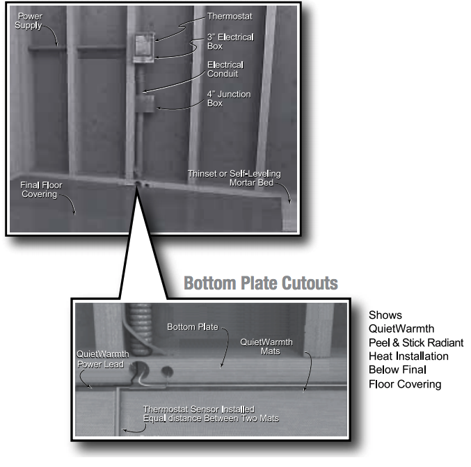
Install Junction box for the control device (thermostat) according to the manufacturer’s instructions. This box should be located, unobstructed, on an inside wall so that the device reads accurately.Install a 4×4 inch junction box for making electrical connections between the mats and thermostat.
Step 4. Bottom Plate Work
Drill or saw holes at the bottom plate. One hole is for routing power leads or conduit and the other is for the thermostat sensor. These holes should be directly below the electrical box(es). It is recommended that you drill or saw holes at the bottom plate. You may also use a notch technique as an alternative.
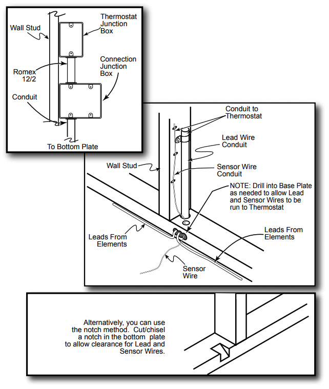
Step 5. Install Power Lead Conduit
Route the power leads from the thermostat down the wall cavity through opening in the bottom of plate to connect the mats.
Step 6. Install Thermostat Sensor
* if thermostat comes with floor sensor
A floor sensor comes with the recommended thermostat control. The sensor wire can be installed without a conduit or in a conduit separate from the electrical power leads if conduit is required by code. Open a second knockout in the bottom of the thermostat box. Feed the sensor (and conduit, if including) through the knock-out, down the wall cavity, through the opening in the bottom plate. Temporarily tape the sensor to the slab or subfloor in a location approximately 6” to 12” from the wall—final location of sensor after mat installation will be taped down at the edge of or in between two mats so that the sensor is not directly above a heating mat. Butt the sensor up against the side of the mat for best results. NOTE: The sensor is located in the thermostat packaging.
Step 7. Rough in the Wiring
Install appropriate electrical wire (conductor) from the power source and breaker protection to the thermostat following all codes. Leave 6” to 8” extra wire at the thermostat box.
Installing the Mats
Step 1. Inspect and Test Heating Mats
Verification that the heating mats were received in operable condition is important prior to installation. When the heating mats are removed from the shipping box, test the resistance using ohm meter and record the information. If the resistance reading varies more than ±3% from the recorded readings on each mat, do not install the mat and contact your supplier for assistance.
Step 2. Preparing the Stable Sub-floor
Clear the floor of all debris, nails, etc. so the floor is smooth, clean and dry.
Cutting & Customizing
Step 1
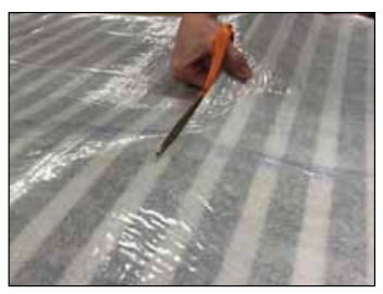
Cut the mat to the required length It is important to only cut BETWEEEN the Black Stripes. Do NOT cut into them as this will cause the GFCI to trip.
Step 2
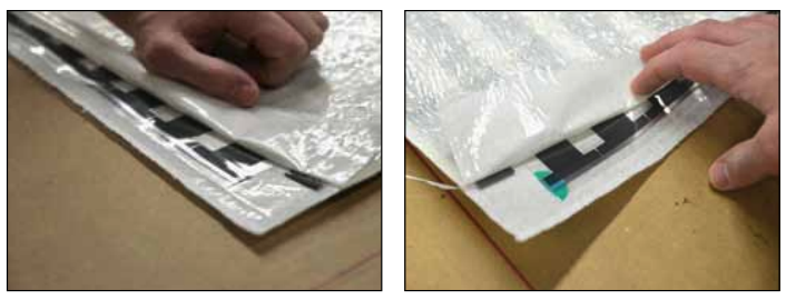
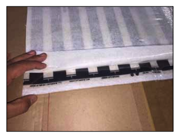
Terminate the end with green insulating discs Cut back one black heat stripe from both ends of the panel making sure not to cut into black stripe. Fold one Kapton Insulating Disk, (Green dots supplied in kit) on the two silver bus bar endings on the panel on the opposite side from the thermostat location. Green insulating disk must be folded over the top and bottom of silver bus bar. Make sure the green kapton disk is covering the bus bar and the black ink area exactly as in the figure.
Step 3
*This step must be done regardless if you are cutting the mat or not. Otherwise it will lead to nuisance tripping of the GFCI and void the warranty.
Sealing the heater by removing the liners.
Fold back and crease the top “flap” on each end of the heating panel(s).
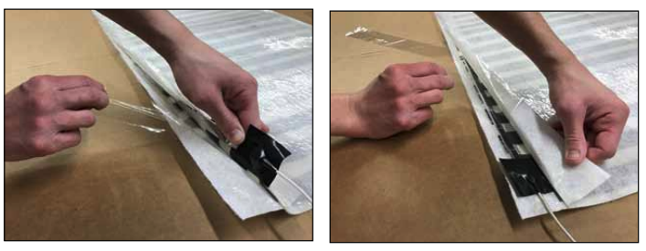
Peel back the bottom release liner on the inside of the flap and adhere the heating element by pressing down firmly.
Once the heating element is adhered to the bottom of the flap carefully peel back the upper release liner and press down to seal the edges of the membrane.
MAKE SURE TO PRESS OUT ANY AIR BUBBLES AS YOU ARE ADHERING THE TOP FLAP TO THE BOTTOM.
Proceed with the rest of the steps for installation on the following pages.
Check the resistance reading again to the new customized size.
Step 3. Laying the Mats
Connection leads from the mats are 15 feet long, and can be cut to desired length to connect at the junction box. The heating mats should be laid so the connection leads are running to the wall of the room where the thermostat/junction box is located. The following steps will guide in the installation of the mats:
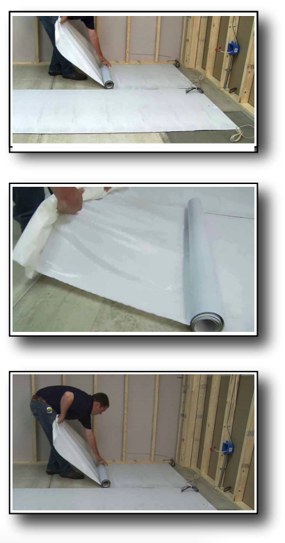
1. With the release liner still on, position all the mats into place. Make sure the leads are within reach of the junction box and that there are no obstructions or floor penetrations in the way. Make sure the position of ALL mats is satisfactory before the next step.
2. When all the mats are in proper position, roll the end with the connections back far enough to peel back approximately 12” (30cm) of the release paper to expose a portion of the adhesive surface.
3. Press this exposed section of the mat onto the surface and then roll the other end back to the point where the release paper was removed.
4. Begin pulling the release liner off and hand smooth the mat into position as it unrolls to achieve a positive bond while avoiding trapping air bubbles.
5. For adjacent mats, follow the same procedure starting with alignment of the side by side mats in a butt joint fashion. Do not overlap mats.
6. Peel off quick release liner and set mat in place, leaving clearance to walls or partitions at the connector end for wiring and final connections.
7. Make sure to seal the flaps on each side of the mat(s). See page 10, Step 3 for directions.
Step 4. Install the Thermostat Sensor
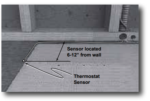 As the mats are installed, locate the thermostat sensor probe. Sensor probe can be held in position with a small amount of tape. The sensor should extend approximately 6” to 12” from wall adjacent to the mat shown. Be careful not to locate the sensor near other heating sources such as a heating duct below the floor.
Step 5. Connect the Electrical Leads
Now, depending upon your wire lead installation, route the lead wires from each of the individual mat along the base of the wall and up to the junction box. Depending on the thickness of the mortar bed, you may also need to chisel a space under the point where the wires connect with the mat in order to recess the connection. Be extremely careful not to damage the heating mat or connection.
NOTE:
The thermostat sensor is thicker than the heating mat. If thin-setting over backer board or slab, saw a groove to recess the sensor to the level of the mat. Use duct tape to secure the sensor in the groove. Do not damage the sensor. Ensure the sensor is set down so it is level with the mat and not on top of the mat. Thermostat Sensor Sensor located 6-12” from wall
A visual and electrical check must be performed on the heating mats prior to activation.
Visual Inspection
Also perform a visual check to look for any signs of damage to the mat or electrical leads that may have occurred during installation. When visually checking the mats, look for any signs of damage, wear, or scratching that might have occurred during installation. If any portion of a mat appears damaged, replace the entire mat. If damage is found, call the technical hotline at 888-WARM-PAD or email [email protected] for advice and/or replacement assistance.
Continuity/Resistance Check
Following installation, a second resistance check across the supply leads of each mat using a digital ohm meter must be made to detect any short or open circuits that may have resulted from the installation process. If the resistance check is the same as the original reading shown on the mat label, the mat is installed properly and no further testing is required.
If the resistance readings are not within ±3% of the indicated value on the mat then call 888-WARM-PAD. If the resistance is ZERO: This indicates a short circuit. Check the path that the wiring is taking and make sure that no wires are pierced or otherwise damaged. Mats with damaged non heating leads must be replaced.
Test for Heating
1. Install control device and connect to electrical panel box. Install and wire the control device according to manufacturer’s instructions.
2. Wire the heating mat(s) to junction box, and wire the junction box to the thermostat according to the manufacturer’s instructions.
3. Turn on the breaker and adjust the thermostat so that it is calling for heat. Refer to the installation sheets provided with the controls for proper setting. After all controls are installed, do not energize the system, except to briefly test operation of all components.
4. After the system has been on for several minutes, run your hand over the heating mats to ensure that they are warm. The heat is a gentle heat and will only heat up slightly until the floor is installed. It will not get hot to the touch. Just a slight warm feeling. The system should now operate as designed. Please leave the instruction sheets for the thermostat in a safe place for future reference.
5. Once heating has been verified, turn off the system.
Final Floor Installation
The mats are now ready for tile installation using a latex modified thin-set with a maximum thickness of 3/8” after the tile is embedded. It is recommended to use a plastic notched trowel to help prevent damage to the heating mat surface. Take care during the troweling process to not nick or cut into the mat or cold lead wires. A continuous circuit monitor alarm can be used to alarm you if the cold lead wires have been cut during the installation. Damaged cold leads can lead to GFCI tripping issues and/or the mat not working. It is best to be sure you haven’t damaged the cold leads before the floor is installed.
We recommend working with professional flooring installers to make sure proper materials are used and proper installation techniques are followed. Install the floor covering according to the manufacturer’s instructions. Use a digital ohm meter to check the rsistance of the mat(s) and sensor(s) before, during and after the installation of the finished floor covering. Record the reading of QuietWarmth® Peel & Stick Radiant Heat on the Heating System Checklist & Warranty Registration Form, continuing to check for short circuits caused by nicks or pinches. If possible, take photographs of the mat installation before installing the flooring.
Tile, Stone, and Marble Installation
When installing QuietWarmth® Peel & Stick Radiant Heat under tile, stone, or marble, we highly recommend Tile Counil of North America (TCNA) guidelines or ANSI specifications for minimum standards of installation. We recommend latex-modified or epoxy modified mortar and grout, instead of water-based multi-purpose materials.
Use full coverage of thin set with no voids. Spot Bonding (Dot Mounting), and leaving large voids, is unacceptable and will lead to a crunching noise where the heat mats are installed. Thin set must be installed following TCNA/ ANSI standards. Spot bonding of tile that only gives partial contact leaving large voids is not an acceptable method for tile installed on floors with thin-set mortars.
Select the proper size PLASTIC trowel for the installation of tile or stone. We recommend a minimum 3/8” x 1/4” trowel. This trowel works best for most 1/4” tile.
If you need more information on tile installation, contact TCNA at (864) 646-8453 or visit their Web site at www.tileusa.com.
Join Our Newsletter
You are about to install your new flooring. As you lay the first plank you realize that